
The purpose of a wheelchair attached support system or mount kit is to securely hold an augmentative communication, speech generating device, laptop computer, tablet, iPad (or anything else really) in the most accessible position for the person using the wheelchair. Access to the technology being mounted is extremely important.
Fitting a wheelchair mount includes many considerations and the location and size for the Frame Clamp attached to the wheelchair frame is often the best place to commence. The relationship between the position of the mounted device and the location on the wheelchair where the Frame Clamp will be attached is essential in ensuring the optimum position for the mounted device. A good place to begin the fitting process.
Generally, when the technolgy being mounted will access directly and the wheelchair is “medium size”, in many cases the parts supplied by the standard Mount Kit assemblies will suffice, as long as the correct Frame Clamp size, shape and features have been identified.
When the technology being mounted is to be accessed via alternative means (used in a scanning, head-pointer or eye-gaze interactions) or when the wheelchair is unusually large or small it is essential that any other additional parts or lengths of tubing are determined as well, however the Frame Clamp is still the first consideration.
You will require an accurate ruler or tape measure, a steady hand and some mathematics in your tool kit to get this done. Here’s how.
Selecting the Attachment Location for the Frame Clamp Inner Piece
All mounting assemblies can be mounted on either the left or right side of a wheelchair, as required by the position of the person seated in the wheelchair or other items attached to the chair (e.g. controllers). The exception is the DAESSY Lockable Rear Folding Mount as one of the parts in this Mount Kit is “handed”, meaning an attachment side must be specified. It is the Lock Mechanism of the Lockable Rear Folding Mount that is specific to either the right or left side of the wheelchair and this side must be specified at the time of order. This does not effect the Frame Clamp which has no “wheelchair side” consideration; Frame Clamps are not “handed”.
On a Non-Tilting Seat System
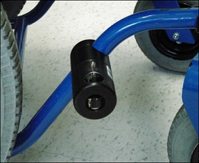
A regular Frame Clamp requires slightly more than 6 cm of wheelchair tube length and about 2 cm of space above and below the wheelchair frame tube to which it will be clamped. There should also be sufficient room for a hand to reach behind the tube to tighten bolts. It does not matter how the wheelchair frame tube is oriented around the wheelchair tube (see the pictures to the right) because the way the rest of the Mount Kit components attach to the the Frame Clamp allows rotation to any angle relative to the Frame Clamp. We can fine tune once we have the Frame Clamp attached but aligning it so the poles of the kit are vertical is important at this stage, so ensure the Frame Clamp hasn’t been rotated too far away from perpendicular to the floor.
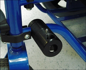
Caution: The selected location must be part of the wheelchair frame, not a removable armrest or footrest.
Often the best location for the Frame Clamp assembly will be near the front caster wheel but preferably not above it. The Vertical Tube for the mount protrudes down through the hole in the Frame Clamp Outer Piece and the range of height adjustment for the mount may be limited if the tube interferes with the caster wheel.
In most situations the Frame Clamp Inner Piece will be located forward or backward from the position for the mounted device and the Vertical Tube supported by the Frame Clamp Outer Piece will have an S-bend.
On a Tilting Seat System
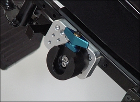
On a wheelchair with a tilting seat system, the mounting assembly should be attached to the tilting seat to maintain positioning of the device relative to the user, independent of the configuration of the wheelchair. On tilting seat systems it is strongly recommended that a parts comprising a Removable Frame Clamp be used – these are the Removable Frame Clamp Receiver (RFCR – which attaches to the Frame Clamp) and the Removable Frame Clamp Outer Piece (ROP – which attaches to the vertical pole). The RFCR is pictured to the right, attached to a MultiHole Adapter on a seat rail.
Obstructions
Obstructions directly above the selected location, such as the brake lever or other controls that are closer than 25 cm, may interfere with insertion and removal of the Vertical Tube. To avoid this interference it may be necessary to use an Offset Link (O3L) or a Frame Clamp Spacer (UFCSPCR). These parts attach to the Frame Clamp and then the rest od the Mount Kit is built from that point. In this way we can adjust the poles further out or position them sideways from the location of the Frame Clamp.
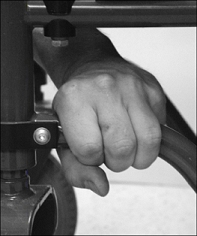
Quick Check
A quick check for a suitable location for the Frame Clamp is to find a part of the frame tube which has enough space to be gripped by three fingers when reaching from inside the wheelchair frame. Very handy!
Unusual Situations
Some wheelchairs do not have any tubing freely accessible on the frame or may not have a tube frame. When a seat pan restricts access to the upper edge of the wheelchair frame tubing, it may be possible to use a Side Mount Frame Clamp Inner Piece, which requires no clearance on the topside of the tube and only 3.5 cm clearance on the bottomside.
There are alternative Frame Clamps that account for many chairs that don’t have this minimum clearance needed. The Side Mount Frame Clamp mentioned above (with code UFC1000SMIP) has it’s 1″ hole offset in the body of the clamp meaning it can clamp to the underside of tubing – handy when the seat pan is in the way. The Front Side Mount Clamp (with code UFC1000FSMIP) is similar to the Side Mount clamp however it’s bolts are on the FRONT of it’s body – handy for when you can’t get to the underside of the chair and must work from the outside.
When the wheelchair does not have a tube frame it may have bolt-holes or other possible attachment methods for a Bolt-on Adapter. Often too, power-base wheelchairs have slots and tracks along their seat frame. Using small parts called T-nuts, which have a cross-sectional shape of a flattened “T” that fits these tracks exactly (thus their name) and threaded holes in it’s body, we can use to bolt-on adapter called a MultiHole Adapter. The T-nut is slid into the track and the MultiHole adapter positioned on the outside of the track. Bolts are connected into ther threaded holes of the T-Nut, through the MultiHole Adapter and together pinch tight on the seat base frame, creating a very solid Frame Clamp attachment point.
Measuring and Specifying the size of Frame Clamp Inner Piece
More information on the range of available Frame Clamp Inner Piece sizes is available in the Frame Clamp Section of the Daedalus Technologies website via this link. For wheelchair frames with round or rectangular tubing it will be necessary to measure the dimensions of the tubing to obtain the correct frame clamp size.
DAESSY Gauge
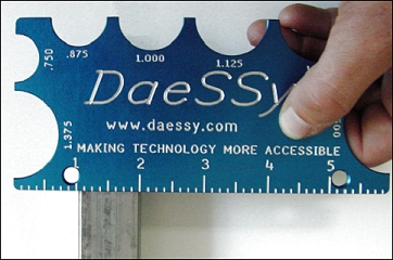
The DAESSY Gauge is a specially designed tool provided with DAESSY Assessment Kits. The calibrated semi-circular cut-outs along three edges of the DAESSY Gauge can be used to quickly determine the diameter of wheelchair tubing. Ask Communicate AT for yours, special orders indeed these days!
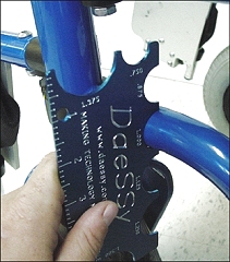
A five-inch ruler with 1/8” gradations can be used to measure the dimensions of rectangular or square tubing. Contact Communicate AT if you’d like to obtain one of these handy gauges yourself.
Other Measurement Methods – Measuring the Tube Size – Round
The preferred method for measuring the exact size of round wheelchair frame tubing is to use a micrometer or dial caliper to directly measure the diameter. “A what ..”, I hear you say.
An alternative method is to measure the circumference of the tube is to use a thin strip of paper, a pencil, and a straight ruler marked in inches are the required tools.
Wrap the strip of paper around the tube so that it overlaps slightly. Draw a line across the edge of the paper to put a mark on both the inner and outer wrap.


Unwrap the strip of paper from the tube and using the ruler measure the distance between the two pencil marks – this is the circumference of the round tube.
The measured circumference can be converted to the corresponding diameter measurement using the following table. If unsure, give Communicate AT a call, we’re asked about this part of fitting all the time.
| Circumference | Diameter | Correct Frame Clamp Size |
| 2.36″ – slightly less than 2 3/8″ | 0.75″ | UFC1000IP or UFC1000SMIP or UFC1000FSMIP +SLV (1″ => 0.75″) |
| 2.75″ – exactly 2 3/4″ | 0.875″ | UFC1000IP or UFC1000SMIP or UFC1000FSMIP +SLV (1″=> 0.875″) |
| 3.14″ – slightly less than 3 3/16″ | 1″ | UFC1000IP or UFC1000SMIP or UFC1000FSMIP |
| 3.53″ – slightly more than 3 1/2″ | 1.125″ | UFC1125IP (or UFC1500IP+SLV) |
| 3.93″ – slightly less than 3 15/16″ | 1.250″ | UFC1250IP (or UFC1500IP+SLV) |
| 4.71″ – slightly less than 4 3/4″ | 1.500″ | UFC1500IP |
| 6.28″ – slightly more than 6 1/4″ | 2″ | UFC2000IP |
Measuring the Tube Size – Square or Rectangular
The dimensions of square or rectangular tube can be measured with a good ruler; normally the square tube will have square corners and the ruler can be held accurately against the tube. It is unusual to find any sizes other than 3/4 inch, 7/8 inch, 1 inch, or 1.5 inch.
Some wheelchairs have what appears to be rectangular tube, but is actually an aluminum extrusion. These nearly rectangular shapes are more difficult to measure particularly when the corners or sides are rounded and it is almost essential to use a proper measuring instrument such as dial calipers. The circumference measurement is not useful for square or rectangular tube.
Bolt-on Adapter and Wheelchair Specific Sizes
See Frame Clamp Inner Piece – Wheelchair Specific Sizes for more information on Frame Clamp Inner Piece styles for some specific wheelchair styles.
Additional Frame Clamp Components
It may be necessary to include extra frame clamp components such as Offset Links or Frame Clamp Spacers to ensure that the mount will not interfere with or contact any other parts of the wheelchair, for example the wheels, brake levers, or power-drive controls. More information on connecting Frame Clamp components can be found on the Daedalus Technologies website via this link.
We hope that helps in a small way. Essentially, the Frame Clamp of a mount kit is the anchor point of the entire “System” including the technology being supported. They are designed to be absolutely rock solid when attached correctly so identifying the most appropriate Frame Clamp for the job at hand is so important.

